


There are only those few simple rules when drwaing Isometric sketcehs with instruments. Follow the guide shown in the picture here and if you need to read about it further look at the Graphics section of this site. If you are doing 'informal isometric sketches' then you fllow the same
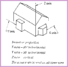
Isometric projection
X- axis - 30 degrees to the horizontal
Y- axis - 30 degrees to the horizontal
Z- axis - 90 degrees to the horizontal
( vertical )
guidelines about angles but they don't need to be done with drawing instruments. This kind of 'sketching' - rather than formal drwaing might be done when developing some of your
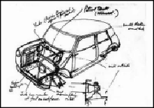
ideas or when showing details of individual details of parts of how systems within your ideas might work. Sir Alec Issigonis's loose sketch of his 'concept' car; the car that was to become an icon in car design - the Mini ; shows just such a use for the ceative transfer of ideas onto paper.
But now look again at the more formal drawings and a few examples of how to complete them.
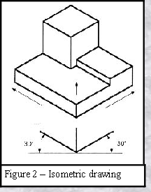
It is possible to pack a great deal of information into an isometric drawing, but Look at the object in figure 2 -shown below - and imagine that it had a hole on the back side. This would not be visible using a single isometric drawing. In order to get a more complete view of the object, a view that includes more detail of the kind that would allow someone lese to make the item using only the drawings to guide them - an orthographic projection may be used.
It is possible to pack a great deal of information into an isometric drawing, but Look at the object in figure 2 -
Orthographic or ‘Multiview’ Drawing
Imagine that you have an object suspended by transparent threads inside a glass box, as in figure 3. This would be a little like having something within a rectangular fish-tank - with the glass surfaces in contact with the sides and the top of the item inside.
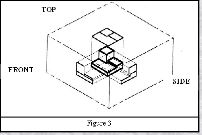
The main rule about the views shown in an orthographic style drawing is that the views are flat representations - only shown from the angles that would be flat-on to those glass panels of
our imaginary fish-tank with the glass surfaces in contact with the sides and the top of the item inside.
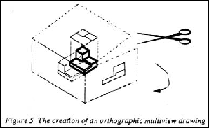
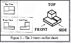
As an exercise now draw the object in figure 2 - as shown in figure 3 - on each of three faces as seen from the direction of viewing. In your mind - unfold the box (see figure 4) and you have the three views - as in Figure 5.

Engineering Drawing and Sketching
for GCSE
for GCSE
