


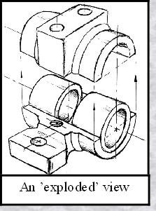
We can also show isometric views of the pillow-block being taken apart or disassembled"
(above – right). This allows you to see the inner components of the bearing system.
Isometric drawings can show overall arrangement clearly, but not the details and the dimensions.
Isometric drawings can show overall arrangement clearly, but not the details and the dimensions.
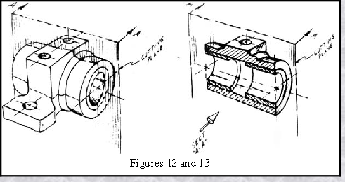
Cross-Sectional Views
A cross-sectional view portrays a cut-away portion of the object and is another way to show hidden components in a device. Imagine a plane that cuts vertically through the centre of the pillow block as shown in figure 12. Then imagine removing the material from the front of this plane, as shown in figure 13.
This is how the remaining rear section would look. Diagonal lines (cross-hatches )
show regions where materials have been cut by the cutting plane.
This is how the remaining rear section would look. Diagonal lines (cross-
show regions where materials have been cut by the cutting plane.

Engineering Drawing and Sketching
for GCSE
for GCSE
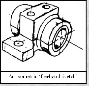
“Assembly" Drawings
An isometric view of an "assembled" pillow-block bearing system is shown on the left below.
It corresponds closely to what you actually see when viewing the object from a particular
angle. We cannot tell what the inside of the part looks like from this view.
angle. We cannot tell what the inside of the part looks like from this view.
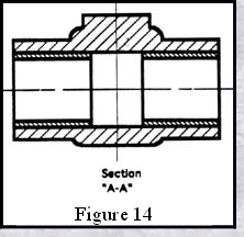
This cross-sectional view (section A-A, figure 14), one
that is ‘orthogonal’ to the
viewing direction, shows the relationships of lengths and
diameters in a much better way. These drawings are easier to make than isometric drawings. Experienced engineers can interpret orthogonal drawings without needing an isometric drawing, but this can take a bit of practice.
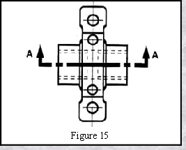
The top "outside" view of the bearing is shown in figure 15. It is an orthogonal perpendicular) projection.* Notice the direction of the arrows for the "A-A" cutting plane.
viewing direction, shows the relationships of lengths and
diameters in a much better way. These drawings are easier to make than isometric drawings. Experienced engineers can interpret orthogonal drawings without needing an isometric drawing, but this can take a bit of practice.
The top "outside" view of the bearing is shown in figure 15. It is an orthogonal perpendicular) projection.* Notice the direction of the arrows for the "A-