


Engineering Drawing and Sketching
for GCSE
for GCSE
IF IN DOUBT ASK !!!!
12th June 2007
One of the best ways to communicate one's ideas is through some form of picture or drawing. This is especially true for the engineer.
The purpose of this guide is to give you the basics of engineering sketching and drawing.
We will treat "sketching" and "drawing" as one. "Sketching" generally means freehand drawing. "Drawing" usually means using drawing instruments, from compasses to computers to bring precision to the drawings. As this is just an introduction, don't worry about understanding every detail immediately - just get a general feel for the language of graphics and drawings. Before starting on any technical drawings, let's get a good look at this block drawing, shown below, from several angles. Any engineering drawing should show everything - a complete understanding of the object should be possible from the drawing without any need for explanations. If the isometric drawing can show all details and all dimensions on one drawing, it is ideal.
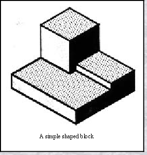

Isometric Drawing
The representation of the object seen
here is called an isometric drawing.
This is one of a family of three-dimensional views called pictorial drawings. In an
isometric drawing, the object's vertical
lines are drawn vertically, and the
horizontal lines in the width and depth planes are shown at 30 degrees to the horizontal.
When drawn under these guidelines, the
lines parallel to these three axes are at
their true (scale) lengths. Lines that are
not parallel to these axes will not be of
here is called an isometric drawing.
This is one of a family of three-
isometric drawing, the object's vertical
lines are drawn vertically, and the
horizontal lines in the width and depth planes are shown at 30 degrees to the horizontal.
When drawn under these guidelines, the
lines parallel to these three axes are at
their true (scale) lengths. Lines that are
not parallel to these axes will not be of
their true length.
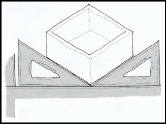
Outline guide to drawing in isometric :
|
·
|
Use a 30 degree / 60 degree set-
|
|
·
|
Use the ‘Parallel motion bar’ ( the horizontal motion bar ) as a support for the edge of the set-
|
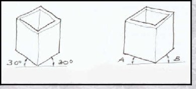
ISOMETRIC (2 angles) TRIMETRIC (3 angles)
In Isometric drawings try to get used to ‘flipping’ the set-square over keeping the longest edge in contact with the horizontal motion bar.
Always keeping the ‘sharpest’ (narrow angle) part pointing either left or right. Only when a 90 degree angle is needed can the sharpest (narrow) angle of the set-square point to the top of the page. Trimetric drawing uses 3 angles.
