


Which views should one choose for a Multiview drawing? The answer is obvious really since the whole point of creating drawings is to communicate information ..... So you should choose the views that reveal every detail about the object. Three views are not always necessary; you need only as many views as are required to describe the object fully.
For example, some objects need only two views, while others need four.
For example, some objects need only two views, while others need four.
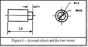
The circular object in figure 6 requires only two views.
In this drawing (Figure 6 - shown here ) something else that is really important has been added. Clearly the round shape could be part of a pen mechanisms - maybe it is the push button at the top of a retractable pen .... Or maybe it is one part of a an oil rig ! Knowing the size of the part begins to give more information that is essential. Measurements have been added and these are shown in millimetres. Using a convention such as this does prevent
IF IN DOUBT ASK !!!!

confusion and possibly costly additional work. You might like to check what implications inaccurate measuring - admittedly on an incredibly fine level - but in an object that was required to have an incredibly small tolerance between what size an item should be and what size it really is - caused in the construction and operation of the Hubble space telescope.
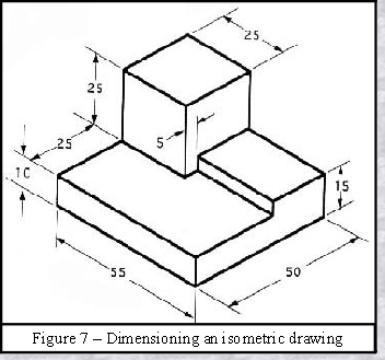
Dimensioning
This object shown in the isometric drawing (figure 7) has been "dimensioned". As a general guideline to dimensioning, try to think that you would make an object and dimension it in the most useful way. Put in exactly as many dimensions as are necessary for the craftsperson to make it – no more, no less. Do not put in redundant dimensions. Not only will these clutter the drawing, but if "tolerances" or accuracy levels have been included, the redundant dimensions often lead to conflicts when the tolerance allowances can be added in different ways.
Note that if drawn to BS specifications Orthographic drawings have dimensions written above an unbroken line or turned through 90 degrees and viewable from the right hand side of the drawing.
Repeatedly measuring from one point to another will lead to inaccuracies. It is often better to measure from one end to various points. This gives the dimensions a reference standard. It is helpful to choose the placement of the dimension in the order in which a machinist would create the part. This convention may take some experience to get right all of the time.
Repeatedly measuring from one point to another will lead to inaccuracies. It is often better to measure from one end to various points. This gives the dimensions a reference standard. It is helpful to choose the placement of the dimension in the order in which a machinist would create the part. This convention may take some experience to get right all of the time.
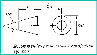
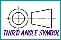
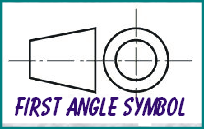
When drawn to ISO or BS specifications
Orthographic drawings have a symbol to
show to which convention - 1st or 3rd angle it has been done. For more on these two conventions use the Graphics section of this site
Orthographic drawings have a symbol to
show to which convention -