


14th November 2010


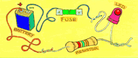
The BATTERY supplies a source of ELECTRONS that make for the flow of ‘electricity’ in the circuit.
The LED (Light Emitting Diode) is the OUTPUT. It cannot take a large flow of electricity and is therefore ‘protected’ by the RESISTOR in the circuit.
The FUSE in this circuit
is being ‘tested‘
... if the light from the LED shows then the circuit has been completed and the fuse is useable in a plug.
If it does not complete the circuit and the LED fails
to glow then the fuse is
‘Blown’ and needs to be
thrown away. (Some fuses have the wire visible)
is being ‘tested‘
... if the light from the LED shows then the circuit has been completed and the fuse is useable in a plug.
If it does not complete the circuit and the LED fails
to glow then the fuse is
‘Blown’ and needs to be
thrown away. (Some fuses have the wire visible)
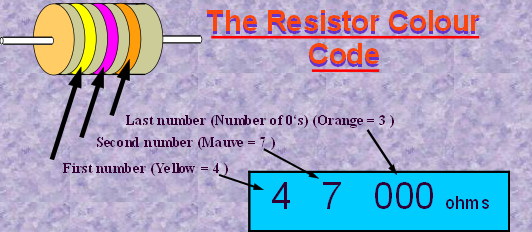
The RESISTOR does just what its name suggests. It ‘resists’ the flow of the
electricity in the circuit. This flow of
electricity is called the CURRENT.
electricity in the circuit. This flow of
electricity is called the CURRENT.
The rest of the circuit is made of an
electrical conducting material. A major
characteristics of metals is that they
conduct electricity so wires usually need to be covered in an insulating material to prevent short circuits. Plastics, wood, paper and ceramics are examples of insulators.
electrical conducting material. A major
characteristics of metals is that they
conduct electricity so wires usually need to be covered in an insulating material to prevent short circuits. Plastics, wood, paper and ceramics are examples of insulators.

Even a very simple circuit like the one shown here demonstrates the
parts of a simple system. INPUT PROCESS OUTPUT
parts of a simple system. INPUT PROCESS OUTPUT
There is nothing too magical about each of the components that we use in electronic circuits. They each have a particular effect on the flow of electrons in a circuit. What is a ‘flow of electrons’ ? Well … that’s what the flow of electricity really is. If you’re not sure what an electron is then don’t worry just think of it as electricity. The BATTERY is a ‘supply of electrons’ and a conducting wire links one part of the circuit to the next. To prevent electrons ‘short-circuiting’ and not following the route we want, insulating material is used. If the flow of electricity needs to be restricted then RESISTORS are used.
IWB Electronics Wordsearch
Download Wordsearch