


14th November 2010


As simple as it is to be turn a switch on with one a simple flick or push it is often more convenient to have a switch operate automatically. Transistors are exactly that – simple electronic switches that can be made to join up two of their contacts by allowing a small flow of electric current to arrive at a third connection. Their invention in 1947 dramatically altered the potential for the creation of more compact, less ’power hungry’ circuits and has led to the availability of infinitely more mobile products like phones, radios and TV’s.
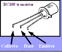
Transistors can be packaged in different metal or plastic cases and also come in several different types - one common type is shown here and the small tag on this ‘npn’ type transistor shows which leg is to be connected to the negative side of the circuit. That leaves two other connections that need identifying. The central one is called the base and it is this that requires the small current to do the switching. The final connection is called the collector and needs to be connected to the positive side of the circuit.
When working with different types of transistor it is important to correctly identify the legs.
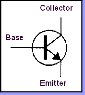
On circuit diagrams the transistor is shown as in the diagram


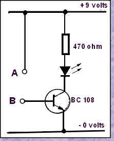
In this simple circuit on the left you should be able to see that joining points A and B will allow a current to flow to the transistor.
What would you expect to happen then ?
From what has already been said – the other two connections would join as if switched on – and this would allow the LED shown in this circuit to light up. There is a ‘limiting’ resistor in series with the LED as a protection – preventing too much current damaging the LED itself.

So now we have a basic circuit that will work by simply joining the two points, to what use could the circuit be put? Well a simple water detector could be made with two steel prongs being joined to the two contacts A and B – with those then pushed into the soil of a plant pot. If the soil was quite wet the LED would glow – green perhaps… If it went out then the soil would need watering.
A fair idea but one that could be improved…….
What changes would you make for a water detector that might make it a lot more useful ?
Check out the Year 9 task.
A fair idea but one that could be improved…….
What changes would you make for a water detector that might make it a lot more useful ?
Check out the Year 9 task.

What would you say would be the best ‘output’ device ?
... A Buzzer or a Constant coloured light ... or a flashing light ?
What might the implications be if the plant were to dry-up during the night ? Would it be possible to adapt the design to make a better product that could take this into account ?
... A Buzzer or a Constant coloured light ... or a flashing light ?
What might the implications be if the plant were to dry-
IWB Electronics Wordsearch
Download Wordsearch