


14th November 2010


Transistors turn on and off as the voltage at the base rises to a level enough to trigger the component. This can be useful if you wanted a light to turn on and off as the light levels rose and fell but what if you wanted an alarm that required to be reset once it had gone off? A transistor in a circuit for a bag alarm wouldn’t be much good since as soon as the stimulus (perhaps the bag being moved ) was removed, then the alarm would stop sounding. A thyristor operates in a similar way to a transistor but stays ‘latched on’ once the stimulus – the trigger voltage, has gone away. Now we can have an alarm or a ‘steady-hand’ game that will give a constant output when the circuit is triggered. To turn it off would need the power source to be disconnected or at least shorted out momentarily.
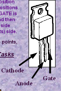
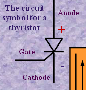
Notice that as before there are 3 different contacts. These do vary in position from one type of thyristor to another but this 106D has the legs in the positions shown here. Viewed from the front with the ‘heat sink’ at the back the GATE is rather like the BASE of the transistor – it waits for the trigger voltage and then joins up the other two contacts. The ANODE is joined to the POSITIVE side
(+ volts) of the circuit – and the CATHODE joins to the NEGATIVE (- volts) side.
(+ volts) of the circuit – and the CATHODE joins to the NEGATIVE (-
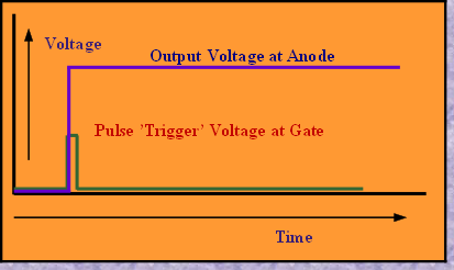
The ’input’ voltage could be just a fraction of a volt whilst the output voltage could be the supply voltage in the circuit. The important feature though is the ‘latching’ on of the component.
The circuit shown on the previous page for transistors would work just as well with the thyristor – but to re-set the system once triggered a switch to 0 volts would be needed from the centre point of the potential divider. Alternatively the circuit could be turned off and then on again.
The circuit shown on the previous page for transistors would work just as well with the thyristor – but to re-
If the trigger voltage is thought of as a pulse, then two simple graphs show what to expect from the thyristor.
So now we have a basic circuit that will work by simply joining the two points, to what use could the circuit be put ?
A steady hand game perhaps - Check out the Year 9 Tasks
A steady hand game perhaps -
IWB Electronics Wordsearch
Download Wordsearch