


14th November 2010
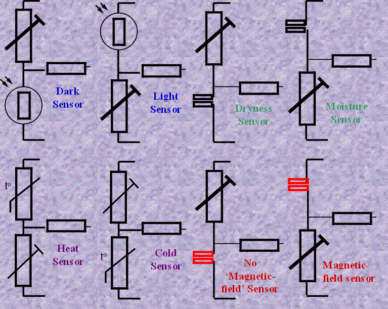


Once the simple potential divider has been set up it can be used to sense a
variety of different input signals. The different components shown her will
give a large variety of different products according to the need chosen.
variety of different input signals. The different components shown her will
give a large variety of different products according to the need chosen.
Using a pre-set resistor a the second half of the ‘potential divider’ allows these circuits to be balanced to the heat-level, light level or whatever the need demands.
Experiment with the values required using a programme like ‘Crocodile Clips’ in which you can build the circuit on computer changing the values of components ‘as you go’
Experiment with the values required using a programme like ‘Crocodile Clips’ in which you can build the circuit on computer changing the values of components ‘as you go’
IWB Electronics Wordsearch
Download Wordsearch