


14th November 2010


A very useful freeware programme (not to be used commercially) that will calculate the values needed to give a particular delay – is available for download here.

Using the 555 Timer, 741 OP Amp and … others
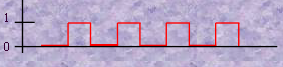
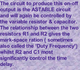
The 555 IC can also be used to generate a series of pulses. If an output state is ‘On’ it can be represented by a ‘1’ and if it is ‘Off’ it can be represented by a ‘0’. This gives the ‘square wave’ pattern seen here where the top sections of the line (the on-periods) are called the ‘MARK’ and the lower sections )the Off-periods) are called the ‘SPACE’ . The number of ‘on-off’s’ in a second is called the ‘FREQUENCY’ of the output. There is a lot on www about the 555 The units of frequency
are HERTZ (Hz) -

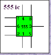
* Pin numbers are always shown – but may for convenience be shown in different positions.


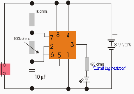
The major point to remember are the different units in use. Frequently the Capacitance will be measured in Microfarads (F x 10-6 ) or nanofarads (Fx10-9 ) and the Resistance in either K ohms (103) or M ohms ( 106). These calculations are just really a matter of moving the decimal point around. A calculator isn’t needed although that will obviously make things very easy.
As was mentioned for the ‘Monostable’ calculations - If you are familiar with scientific notation then adding the powers easily gives the answer. If you prefer to move the 0’s - simply cross off each of the 0’s to the right of the decimal point as one from the left of the decimal point is crossed off. ( Remember the last two 0’s shown here on the Capacitor’s value would not be included as 0.000100 is really 0.0001. Once the decimal point is reached then the 1 will move to the other side of the decimal point and then 0’s will be tagged on.
Graphic illustration of the on and off sequence produced by the ‘astable’
IWB Electronics Wordsearch