


14th November 2010

10


Using the 555 Timer, 741 OP Amp and … others
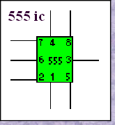
The 555 timer has eight pins – It is a DIL package (Dual In-Line) - It as two rows of four pins in-line ! It may seem hard to remember which pins are connected where – but start by getting rid of two of them. Pins 1 and Pin 8 – These connect to the power connections: Pin 1 to the negative and Pin 8 to the positive. Its getting better since now we have fewer to remember. Try now to remember that pin 2 is the Input and Pin 3 the Output - we have allocated half of them already !

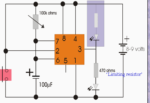
The grey area shows the position for the output LED if the effect required is for the LED to stay OFF for the required time delay rather than ON – the position shown without shading.
This circuit is the basic
MONOSTABLE layout and will be controlled by the variable resistor and the capacitor.
Basically the larger the values of both – the longer will be the time delay.
This circuit is the basic
MONOSTABLE layout and will be controlled by the variable resistor and the capacitor.
Basically the larger the values of both – the longer will be the time delay.
* Pin numbers are always shown – but may for convenience be shown in different positions.
The time delay can be calculated by simply multiplying the value of R1 with the value of C1. This is known as the Time Constant.
Tc = 1.1 x R1 x C1
One major point to remember in calculating Time Constants is the units that are being used. Most frequently the Capacitance will be measured in MicroFarads (F x 10-6 ) And the Resistance in either K ohms (103) or M ohms ( 106). These calculations are just really a matter of moving the decimal point around. A calculator isn’t needed although that will obviously make things very easy. The answer units will be in ‘seconds’
If you are familiar with scientific notation then adding the powers easily gives the answer. If you prefer to move the 0’s - simply cross off each of the 0’s to the right of the decimal point as one from the left of the decimal point is crossed off. ( Remember the last two 0’s shown here on the Capacitor’s value would not be included as 0.000100 is really 0.0001. Once the decimal point is reached then the 1 will move to the other side of the decimal point and then 0’s will be tagged on.
10
10
10
10
A very useful freeware programme (not to be used commercially) that will calculate the values needed to give a particular delay – is available for download here.

5
-4
5
-4
1
IWB Electronics Wordsearch